A P-O-X On Both Your Houses: Reverse Engineering a 20 year RF protocol

In 2001 Hasbro began a viral marketing campaign for their new game, P-O-X. They started in the Chicago area, asking kids — in arcades, in schools, at skateparks — who they thought the coolest kid¹ at that location was. They continued up the chain until they found someone who thought of themselves as the coolest, and gave them copies of the game. The success of this campaign was such that Toys R Us backed a national launch, set for late September of that year.
However, 2001 ended up being a year in which a game about disease-themed aliens invading the earth was seen as in bad taste by higher ups at Toys R Us for… a number of reasons, (check out the commercial for yourself) and the game was pulled from the market, with an overall lifetime of under a year.
The game itself wasn’t all that complex. It came in three varieties of “PCU” (the name for the handheld unit), each with a different color. You played single player levels to unlock one of three types of parts (head, body, tail), and used them to assemble a little alien. Each different colored iteration of the game had different parts available, very Pokémon-esque. You gave the alien a name, and critically, defined a tiny AI routine for how the alien fought — the game called this routine a “WAD”.

The “WAD” system was represented by a 3x3 matrix. Each row represented one attack sequence, in which you chose 3 body parts— first, a body part of your own to attack With, then, a body part of your opponents’ to target your attack At, finally, one of your own to Defend. Your alien would repeat this attack sequence until any one body part reached 0 HP, at which point, that alien would lose. This was relatively obtuse feeling as a child, and rather unpredictable as an adult, but it served its’ purpose.

Something that, at the time, seemed magical was it’s multiplayer model; Pox allowed asynchronous, wireless, interaction-free battles. You simply enabled the “fight” mode, and your little disease monster would go beat up everyone in range using it’s preprogrammed WAD. Compared to the rigmarole of getting our Game Boys hooked up for a Pokémon battle, it was positively refreshing.
I always wondered how exactly it worked, and I’ve wanted to play around with a radio-based reverse engineering project for awhile, so this seemed like an apt opportunity. After eBaying half a dozen copies of the game, I got to work.
All code produced for this project is available here.
Step 0: Oh God What Am I Even Doing
Our goal, overall, is to identify and retrieve a bunch of bits from the air. To do that, we need to figure out a couple of characteristics of signal we’re analyzing. Some important bits of information are:
- Frequency: That is, where on the spectrum your device is broadcasting, measured in Hz, so we know where to listen.
- Modulation and (maybe) Encoding: How your 1s and 0s are mapped to the sinusoidal structure of a radio wave, and if there’s any transformation on them to avoid long runs of 1s or 0s.
- Baud Rate: How many bits per second are being expressed into the air.
Given these pieces of information, you can begin to pull bits out of the air, and build packets for analysis.
Except, important question: What does any of that actually mean?
Step 0a: How does radio actually work?
Radio signals are inherently an analog phenomenon — they’re high frequency electromagnetic waves put into the air. RF communication is the process of measuring properties of these waves, and using those properties to extract digital 1s and 0s.
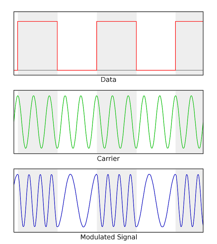
The basis of these signals is what’s called a carrier wave, a pure electromagnetic wave of a given frequency. As you might imagine, a standardized wave inherently has no information, this is where “Modulation” comes in. In a digital signal sense, modulation is the process of varying the properties of a radio signal between two states that we can detect and translate to 1 or 0.
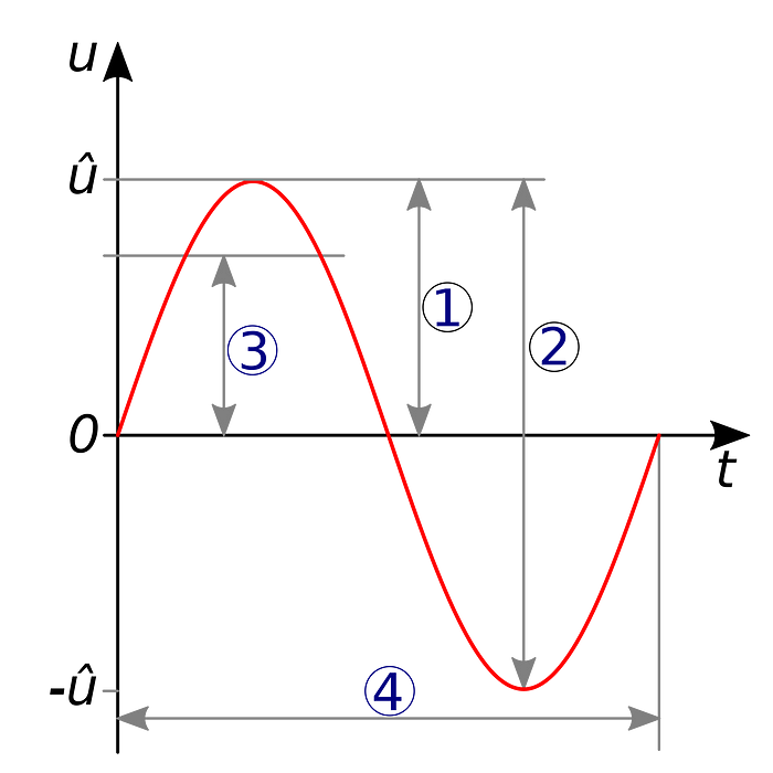
What properties? There are a number of options, but the two most common are frequency, and amplitude, and these give rise to Frequency Shift Keying (FSK) and Amplitude Shift Keying (ASK). You may also be familiar with the terms AM (Amplitude Modulation) and FM (Frequency Modulation), which are used to describe the analog versions of these techniques.
In FSK, the frequency of the signal is changed, with one value representing a 0, and another a 1. The frequency changes between two values, and the transition from one to the other is detected as a change from a 0 to a 1.
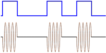
In ASK, the amplitude of the signal varies. Amplitude generally is a measurement of the broadcast power of a signal — higher power, higher amplitude. A common form of ASK, OOK (On-Off Keying), involves entirely stopping transmission to represent a 0, and broadcasting at a set power to represent a 1. By measuring the presence or absence of signal, you can detect a 0 or a 1.
Generally, the period of these signal modulations is regular. If a high frequency or amplitude for 100ns represents a 1, then we expect a 0 to be represented by a lower frequency/amplitude for 100ns.
So to put it all together — We are going to measure all the radio signals present at a given frequency, and analyze their traits, such as amplitude and frequency, to look for periodic changes we can map to a digital signal. We expect the duration of these periodic changes to be consistent, and this gives rise to the baud rate, which expresses the overall data rate of the signal. The baud rate can also be derived from observations of the underlying signal and the duration of a 0 or 1.
So, now that we have a basic understanding of what we’re looking for… how do we get these pieces of information? There’s a few ways — such as just capturing and eyeballing the signals and discerning their properties by hand, but, rather than do all that work ourselves, we can take a few shortcuts.
Step 1: Open Source Intelligence
A common first step in a project such as this is called “Open Source Intelligence”, that is, analysis of publicly available documents to understand details of the behavior of the system you’re analyzing. Any device that emits radio signals has to be registered with the FCC, and any piece of hardware with significant R&D is likely to be patented. Documents from these applications are publicly available, and often contain interesting details.
The FCC Listing is rather boring — it really only tells us one detail, the frequency, 315 MHz. However, the patent is an absolute treasure trove. If you have the time, I recommend reading through it, there’s multiple pages of backstory, tips and tricks, listings of all the various parts in the game (or at least, early iterations of them). It’s a veritable Prima Strategy Guide.
However, the patent is also overly ambitious, to say the least. The game has only a tiny fraction of the features described , and many — trading, giveaways, OTA updates (yes really) — don’t seem to have ever been implemented². In addition, while there are staggeringly specific technical details — memory layouts, packet structures, command codes — many of these implementation details have different, conflicting implementations suggested, meaning we have to pick through the options and figure out what seems most likely.
To start, let’s extract some choice quotes and pick through things:
- [0013] “315 MHz with a data transmission rate of 12 kbps.”
- [0146] “The bi-simplex communication protocol may use a single frequency for transmitting and receiving data. This implementation includes data integrity checking; however, data forward error correction is not used. The packet data payload in this implementation is 64 bytes with a 2-byte cyclic redundancy check (CRC).”
- [0147] “The communication protocol shown … may be implemented using a 10 second minimum period between packet transmissions and a maximum packet length of 333ms. …The data transmission rate using this protocol is 1.17 Kbps when data that is Manchester encoded using On-Off Keying (OOK).”
- [0153] “In some implementations, data may be repeated four times per packet to provide ample bandwidth for OOK or FSK data transmission of NRZ-I data. Other data formats, such as Manchester encoding, may be used to make a more robust channel without substantially adding to the data rate.”
- [0158] “In this implementation, sniff cycles are timed to ensure a high probability of detection of a transmitted POX packet. This can be adjusted by using sync/framing structures in the packet, or by multiple transmissions of the same data in a packet.”
- [0162] “Transmit mode formats the data packet, including sync bits, check bits, and redundant data, and passes this information serially to the RF transmitter. There is no check for a successful transmission,”
To summarize, based on the details we can make guesses at the values we need:
- The frequency is 315 MHz, confirmed by the FCC filing.
- The modulation is either FSK (Frequency Shift Keying) or OOK (On Off Keying) with Manchester Encoding
- The baud rate is either 12 kbps or 1.17 kbps.
Given the fact they only mention FSK once, and OOK twice (and provide more details on the implementation) it seems more likely to be OOK. This modulation tends to be more common for these sorts of devices, and is a good working theory.
Finally, 12 kbps is quite a lot given the amount of data they claim to need to send per operation, so I suspect while they could in theory push 12 kbps with the hardware they’re using, in practice, the 1.17 feels too oddly specific to not be a real implementation detail.
There’s a few other details — CRC bytes, repeating the packet multiple times, sync bits, and so on — to also keep in mind as we attempt to understand the overall packet structure and protocol. As with the other details, it’s likely only some of these actually play a part, but it provides us a nice menu of options to start with.
So with that, we have good working theories for our frequency (315 MHz), our modulation and encoding (OOK with Manchester Encoding) and our baud rate (1.17 kbps), all without actually touching a radio.
Let’s go validate these assumptions.
Step 2: Signal Analysis
To start off, let’s talk about my toolkit — I started with what I had on hand, an RTL-SDR dongle as my SDR and a Flipper One to attempt replaying captured packets. In terms of tools, I found GNU Radio and Inspectrum to be the most useful, though thanks to the wonderful SDR community there’s a whole bunch of options here.
So, with that, let’s get into it.
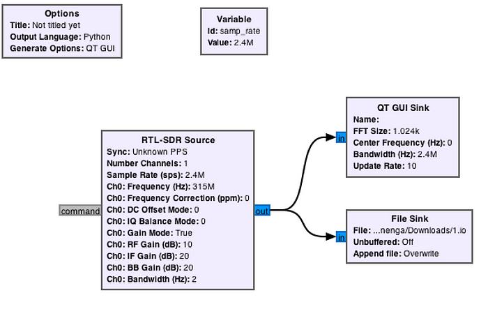
GNU Radio is a powerful tool that allows you define flow graphs to transform and clean up radio signals in a bunch of ways. The flow graph I have defined is very simple however, the goal here is not automation, but simply getting data I can pipe into inspectrum for analysis.

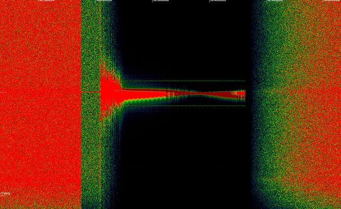
Looking at the signal in inspectrum, bursts of high strength signal and regular pauses — clear indicators of OOK modulation.
With a well configured amplitude plot, we get a nice square wave. One thing to note in the signal is we’re seeing no more than 2 sequential 0s or 1s, which is indicative of Manchester encoding, as stated in the patent. Finally, when we leverage inspectrum’s cursor tools, we can see that, indeed, as expected, the baud rate is approximate 1.17 kbps.³
All this put together means we’re finally ready to translate our radio signals into binary. While I could have used GNU Radio to do this, I recently picked up a Flipper One, and decided to give it a shot as it natively supports demodulating OOK signals.
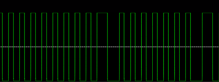
The Flipper outputs data in terms of the duration the signal is in a 0 or 1 state based on the demodulation logic you specify when capturing. The system does it’s best to minimize noise, but we do get random 1/0 transitions throughout durations where the Pox isn’t broadcasting.
Which leads us to a question: How do you separate signal from noise when doing automatic processing? While it’s pretty easy to manually parse it out when looking at inspectrum, we need an algorithmic approach.
This problem is solved by two common patterns in broadcasting digital signals: Preambles and sync bits.
The preamble is a series of 1 to 0 transitions that repeat at our baud rate. The point of this is to communicate “Look out, I’m about to start broadcasting a packet”. The preamble lasts for awhile (33 bytes worth here) before we reach the sync bits. The sync bits mean “the preamble is ending, the following data is the packet”.
In our case, our sync bits are “1100”. How do we know this? Earlier, we determined that our data was Manchester encoded. Both 11 and 00 are illegal bit patterns under that encoding, meaning they could not possibly be part of the actual packet.
So in summary, we wait for repeating 0 and 1 at our expected pulse duration, and wait until we see the bits “1100” and then start consuming Manchester encoded bytes. The packet length is still an open question, and while the patent details several possible packet structures, none of them seem to be correct. In practice, we again look for data that is not a legal Manchester encoding, and find that we start seeing runs of 0s after 40 bytes of data, implying that is our packet size. We could also confirm this with inspectrum, but eyeballing the demodulated bitstream was good enough for me.
Putting this all together, I build a python script to detect the preamble and sync bits, extract the 40 bytes of encoded data, and begin building a corpus of packets.
Step 3: Protocol and Binary Analysis
So to start off, we need to figure out how the protocol works. We define the protocol as the type of packets sent, and the order they’re sent in. The patent discusses a few potential approaches. Many of them reference mechanics and behaviors (currencies, trading) that aren’t in the final game, so narrowing it down to ones that match the game’s actual scope, there’s two protocols. The basis of each is similar; each unit broadcasts the details of their Pox (IE parts, HP, WAD, etc) and a battle takes place. The differences are in one protocol the fight doesn’t take place until one unit receives a response message from the other, and in the the other protocol, only a single packet is sent by each unit, and each unit processes battle results independently.
So, before we even look at the data, let’s craft a hypothesis. The Pox game logic is wholly deterministic, and there’s no player interaction during battles. The transmitters are low power, and players can be far away, meaning noise and missed packets are a real concern. Because of this, I’m leaning towards the single packet model.
When we look at the data, we see that theory borne out. When a single unit is broadcasting, it repeats a single packet. When you have two units broadcasting, each broadcasts the same packet as they do when broadcasting alone, with no changes.
So, if only one packet is broadcast, then we know each packet has to include all the data needed to perform all game functions. We have 20 bytes to work with once we’ve decoded the data.
When reversing a binary format, the thing to understand is that, except in extraordinary cases, the formats generally don’t have significant obfuscation. They’re structured such that they match standard behaviors for the hardware (endianness, word size and alignment, and so on), and sensible for the developers working on the system. All to say, you can generally make a lot of progress by starting from what would be the most straightforward approach if you were building it yourself.
So with that perspective, let’s analyze what relevant data is needed to process a fight. When you set up a Pox, you set a PCU ID, a player name, and you create a Pox, consisting of a head, body, and tail. Finally, you set a name for your Pox.
When you battle, you clearly need to send the ID of your head, body, and tail, as well as their respective HPs, which the manual says can go up to 500. You also need to send your WAD. The manual mentions two players with the same PCU ID can’t fight, so the ID of your PCU must be sent. When you win or lose a fight, the name of the Pox that you battled is displayed, so that’s in the packet too. Finally, POX came in three colors — blue, red, and green — and certain body parts have different behaviors when you fight a pox of a given color, so we need to send the color of our PCU.
Let’s start by assuming each value is a byte. We have 20 bytes to work with, let’s see if that all fits:
- 3 bytes for the body parts
- 6 bytes for HP — the value is above 256, so we can’t fit it in one byte
- Names and IDs are exactly 6 characters, so 12 bytes total
- There are 9 values to a WAD, so 9 bytes
- PCU color has 3 options, and would be sent as a byte
This puts us at 31 bytes, we’re over budget by 11 bytes. So unsurprisingly for this sort of use case, the developers must have been fairly economical with their space. Let’s take a step back and figure out the minimum bits for each value.
- The manual numbers the body parts up to 189. This means we need a byte such that we can represent values up to 256, so 3 bytes total, or 24 bits
- HP needs 9 bits per value (to support a max of 500), so 27 bits for the 3 body parts.
- The character set for names and IDs is capital letters, numbers, and space, or 37 characters, which fits into 6 bits. In total, for the two strings, we need 72 bits.
- WADs have 3 potential values for each slot (Head, Body, Tail), meaning they can be represented with 2 bits each. There are 9 WAD values, so 18 bits total.
- There are 3 options for PCU color, so we need 2 bits to represent that.
Adding this up, we get 143 bits, well within our 20 byte/160 bit budget. The patent mentions a 2 byte CRC value, which, if present, would bring us up to 159! Almost perfect. We don’t know if this is wholly correct, but it’s a good hypothesis to work from.
Lastly, before we get started looking at data, we need to have a theory for the text encoding. My first thought was ASCII, but if we’re truly only using 6 bits, then this is impossible as capital characters require the full 8 bits to represent. Like many reverse engineering projects, you can learn a lot by just inspecting how the system works. Text in POX is entered not with a keyboard, but by scrolling through a list of characters. You start with A, work through the alphabet to numbers, and end with space. So, the simplest answer is A = 0, B = 1 and so on, ending with space = 36. This is an efficient and straightforward encoding for this use case, and is the most likely option given what we know now.
Alright, with that, we can actually start analyzing the binary. On a green PCU I created a pox with the name and ID “AAAAAA”. All pox body parts start with 30 hp, and my WAD was “HHH, HHH, HHH”. This message repeated, and did not change when I reset my PCU
01 01000000 -> 32
02 00011110 -> 30
03 01001111 -> 79
04 00011110 -> 30
05 01100111 -> 103
06 00011110 -> 30
07 00000000
08 00000000
09 00000000
10 00000000
11 00000000
12 00000000
13 00000000
14 00000000
15 00000000
16 01000000 -> 64
17 00000000
18 00000000
19 00000011 -> 3
20 00001010 -> 17
So immediately, we can pick out our HP values. Pox parts are numbered and the 32/79/103 values match my head/body/tail part numbers. So, the first 6 bytes seem to represent your Pox’s parts, and it’s HP. Oddly, though HP can go up to 500, there isn’t space to store that given the packet layout. We’ll have to get a part to over 255 HP later so we can figure out how it represents that.
If our theory about text encoding is right, the 0s are exactly what we expect for the name and ID. We don’t know the exact positions yet, but so far our theories are looking good.
As for WADs, much like text encoding, you select the values via scrolling through a list The order is H, B, T. So, we can assume that Head = 0, Body = 1, Tail = 2.
The 3 and 17 don’t map to anything we expect. At this stage, assuming they’re a CRC is a good bet. We can test that with this lovely tool. We put in all our bytes (other than the potential CRC ones) and, wouldn’t you know it — we get a match when using CRC-16/XMODEM.
Finally, the 64 is a bit odd. Looking at our theories about the data representation, we see we have byte values, 6 bit values, 2 bit values, and 9 bit values. Assuming the developers wanted to keep things aligned to bytes, and they wanted to use their space efficiently, what must be happening is 6 bit values are being combined with 2 bit values (and perhaps the “extra” bit from the 9 bit values) and being stored as one byte. From our initial hypothesis, the only value that’s unaccounted for is the PCU color, so at this point, it’s a reasonable guess to say the upper 2 bits of the 16th byte stores the PCU color. We can test this later by setting up the same configuration in a differently colored PCU. So, currently, our mapping looks like:
01 01000000 Head Part ID
02 00011110 Head HP
03 01001111 Body ID
04 00011110 Body HP
05 01100111 Tail Part ID
06 00011110 Body HP
07 00000000 ???
08 00000000 ???
09 00000000 ???
10 00000000 ???
11 00000000 ???
12 00000000 ???
13 00000000 ???
14 00000000 ???
15 00000000 ???
16 01 000000 PCU color?, ???
17 00000000 ???
18 00000000 ???
19 00000011 CRC
20 00001010 CRC
So, what now? Simple, we pick a variable or two, we change it, and we validate our current theories against the new data.
So, I took a green PCU, changed the ID to “BAAAAB”, and got:
01 01000000 Head Part ID
02 00011110 Head HP
03 01001111 Body ID
04 00011110 Body HP
05 01100111 Tail Part ID
06 00011110 Body HP
07 00000001 ???
08 00000000 ???
09 00000000 ???
10 00000000 ???
11 00000000 ???
12 00000001 ???
13 00000000 ???
14 00000000 ???
15 00000000 ???
16 01 000000 PCU color?, ???
17 00000000 ???
18 00000000 ???
19 00000000 CRC
20 01111111 CRC
Bytes 7 and 12 changed from 0 to 1. This makes it quite likely that these bytes include the ID characters, and our theory about the text encoding was correct. We can validate this further by testing with the ID “ AAAA “, where bytes 7 and 12 do indeed become 36, as expected. This confirms our theories. Thus, our new schema looks like:
01 01000000 Head Part ID
02 00011110 Head HP
03 01001111 Body ID
04 00011110 Body HP
05 01100111 Tail Part ID
06 00011110 Body HP
07 00 000001 ???, ID Char 1
08 00 000000 ???, ID Char 2
09 00 000000 ???, ID Char 3
10 00 000000 ???, ID Char 4
11 00 000000 ???, ID Char 5
12 00 000001 ???, ID Char 6
13 00000000 ???
14 00000000 ???
15 00000000 ???
16 01 000000 PCU color?, ???
17 00000000 ???
18 00000000 ???
19 00000000 CRC
20 01111111 CRC
Just pattern matching, we can also guess that the next 6 bytes store the name of the Pox in the same manner. So, we test this by creating a Pox with the name “BAAAAB” and when we do, we get the expected changes in bytes 13 and 18. So, our current schema looks like:
01 01000000 Head Part ID
02 00011110 Head HP
03 01001111 Body ID
04 00011110 Body HP
05 01100111 Tail Part ID
06 00011110 Body HP
07 00 000000 ???, ID Char 1
08 00 000000 ???, ID Char 2
09 00 000000 ???, ID Char 3
10 00 000000 ???, ID Char 4
11 00 000000 ???, ID Char 5
12 00 000000 ???, ID Char 6
13 00 000001 ???, Name Char 1
14 00 000000 ???, Name Char 2
15 00 000000 ???, Name Char 3
16 01 000000 PCU color?, Name Char 4
17 00 000000 ???, Name Char 5
18 00 000001 ???, Name Char 6
19 01010110 CRC
20 10001011 CRC
By further varying name character 4, we do indeed get the expected result — a change to only the lower 6 bits — and we can confirm our theory about packing multiple values into one byte.
Two more things to test. First, we can validate our theory about byte 16 including the PCU color. I set things up identically to my last test on a blue Pox:
01 01000000 Head Part ID
02 00011110 Head HP
03 01001111 Body ID
04 00011110 Body HP
05 01100111 Tail Part ID
06 00011110 Body HP
07 00 000000 ???, ID Char 1
08 00 000000 ???, ID Char 2
09 00 000000 ???, ID Char 3
10 00 000000 ???, ID Char 4
11 00 000000 ???, ID Char 5
12 00 000000 ???, ID Char 6
13 00 000001 ???, Name Char 1
14 00 000000 ???, Name Char 2
15 00 000000 ???, Name Char 3
16 10 000000 PCU color, Name Char 4
17 00 000000 ???, Name Char 5
18 00 000001 ???, Name Char 6
19 01110000 CRC
20 01111100 CRC
We see the first two bits of byte 16 change to 10 from 01. This implies blue = 2, green = 1 and red (hopefully) = 0. I run a final test on a red PCU, and get the expected result.
Finally, we need to figure out how WAD values are represented. Seeing there are 9 bytes with an unmapped upper 2 bits before PCU color in byte 16, my theory is a WAD of “BBB, BBB, BBB” will result in 1s in those slots.
01 01000000 Head Part ID
02 00011110 Head HP
03 01001111 Body ID
04 00011110 Body HP
05 01100111 Tail Part ID
06 00011110 Body HP
07 01 000001 WAD index 0, ID Char 1
08 01 000001 WAD index 1, ID Char 2
09 01 000001 WAD index 2, ID Char 3
10 01 000001 WAD index 3, ID Char 4
11 01 000001 WAD index 4, ID Char 5
12 01 000001 WAD index 5, ID Char 6
13 01 000000 WAD index 6, Name Char 1
14 01 000000 WAD index 7, Name Char 2
15 01 000000 WAD index 8, Name Char 3
16 01 000000 PCU color, Name Char 4
17 00 000000 ???, Name Char 5
18 00 000000 ???, Name Char 6
19 00101001 CRC
20 01101100 CRC
Exactly as expected! Testing with a “TTT, TTT, TTT” WAD also has the expected sequence of 10s in that slot.
At this point, we’ve mapped nearly the entire structure. There are 4 bits that are always 0 so far, and the only open question left is how HP values over 255 are represented. It stands to reason that 3 of those bits are the 9th bit in the HP values, but the 4th is a mystery. Body part HP values change from their base of 30 with a somewhat convoluted process.
When you win a fight, you get to “dissect” the defeated Pox. The body part you get from this process has its’ HP increased by 10. To my knowledge there is no other way to raise HP for body parts. Doing that legitimately is going to be… difficult. So, instead, we’re going to cheat, and that means we have to start transmitting our own packets.
Step 4: Broadcasting and Schema Finalization
While my Flipper One can replay messages I’ve received, constructing files, transferring to the device, and then playing them back was rather cumbersome. So I picked up a Yardstick One which works with the rfcat⁴ library to act as my transceiver.
I used the construct library to define a schema like so:
from construct import Struct, Int8ul, Bytes

PoxAdvertiseStruct = Struct(
    "head_id" / Int8ul,
    "head_hp" / Int8ul,
    "body_id" / Int8ul,
    "body_hp" / Int8ul,
    "tail_id" / Int8ul,
    "tail_hp" / Int8ul,
    "wad0_id0" / Int8ul,
    "wad1_id1" / Int8ul,
    "wad2_id2" / Int8ul,
    "wad3_id3" / Int8ul,
    "wad4_id4" / Int8ul,
    "wad5_id5" / Int8ul,
    "wad6_pox_name0" / Int8ul,
    "wad7_pox_name1" / Int8ul,
    "wad8_pox_name2" / Int8ul,
    "pcu_color_pox_name3" / Int8ul,
    "unknown1_pox_name4" / Int8ul,
    "unknown2_pox_name5" / Int8ul,
    "crc" / Bytes(2)
)
“Int8ul” represents an integer of 8 bits, unsigned, and little endian. I use ints everywhere here because all the values so far resolve to ints (WADs, characters, colors, etc). I could have pulled the packed values apart via construct, but the interface for non-standard integer sizes isn’t amazing, and masking and shifting work well enough to extract what I need.
I then began constructing packets. This was a 3 step process:
- Generate packet bytes using the construct schema
- Manchester Encode the bytes
- Prepend the preamble and sync bits (remember those?)
Finally, I use rfcat to broadcast this to a Pox with RF mode turned on, and… It works! The PCU picks up my fake pox packet as though it were a real unit. We can now construct our own packets, and start building some interactive AIs.
But first, we need to finalize the schema by manually toggling bits we couldn’t discern earlier. As theorized, the first 3 unknown bits are the 255 bit for the head, body, and tail HP, respectively.
The final unknown bit was a bit harder. Simply setting it to 1 causes our packets to get ignored. After a bunch of experimentation, I was able to figure out how the game uses it: When your Pox defeats another one, the winning Pox takes up temporary residence in the losing PCU as an “invader”. This invader, much like a virus, hijacks your PCU to broadcast itself. If your Pox is defeated by one of these invaders, a packet is sent out with the defeated Pox’s characteristics, and that final unknown bit set to 1. It’s not clear to me who sends this — the defeated PCU or the invading PCU, or what PCUs do when they receive these messages. I’ll continue to experiment, but it’s certainly odd.
That said — it’s not all that important, we have most of the functionality mapped out. What IS important is what we can do with our complete schema.
Step 5: Bullying
When I set out on this project, I had a very specific goal in mind: I wanted to produce an unbeatable Pox AI that I termed “bully mode”. Since your WAD, your little “AI” program to operate your Pox, is sent with your packet, in theory you could get a packet, read their strategy, and respond with a crafted Pox to crush theirs.
So I did it.
The actual implementation isn’t complex. It attacks the weakest part you’re not defending, and defends wherever you attack. This may be beatable/exploitable if you craft a Pox with abilities that can exploit this, but that’d be pretty difficult (and it could of course, be detected and countered if we wanted to).
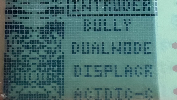
Overall made 3 AIs:
- Bully Mode — Reads your strategy and cheats to become unbeatable.
- Gift Mode — The opposite of bully mode, they just feed you wins. Good for giving parts to a “real” PCU
- Randy — Totally random! Perfectly replicates my Pox strategy as a kid.
Goal accomplished — So what now?
Steps Beyond: Fuzzing and Further Mysteries
So the question I’m sure many of you are wondering is “Can you crash a Pox?” and the answer is… I don’t actually think so. Packets are fixed length, with no variation the structure that I can detect, and there’s only 1 type of packet I’ve been able to observe. Passing in values outside the ranges expected, or futzing with the CRC just causes the packet to be ignored.
But that said, there’s some tantalizing stuff in the patent. Much of it seems like speculative bunk (trading, etc) but there’s a few things that catch my eye:
- [0140] POX supports several hidden user interface screens that are used to facilitate diagnostics, to gather statistical information, to update the product, and at points of sales. These are accessed either by special key sequences or by a specific command sequence sent through a communications port (either wireless or wired). Most of the hidden user interface screens do not respond to button presses; they are active for a defined period of time. When a hidden screen is complete, the PCU automatically returns to the company splash screen.
- [0170] Feature activation is a non-PCU command that permits third parties to activate additional features such as hidden prions or other areas of the game. A security system verifying a valid transaction recipient is used to prevent unauthorized users from enabling these additional features. This functionality is described in FIG. 23. Feature activation can be used in marketing and partnership campaigns. For example, it could be used to allow a retail store to enable additional features if customers bring their PCU to the retail store.
- [0172] FIGS. 25 and 26 illustrate two additional non-PCU command codes that provide a mechanism for uploading and/or downloading the POX database. This provides an upgrade path so that individual POX units can be loaded with a newer version of the POX software or with another game.
OTA updates? Activating hidden features? Interesting.
Looking at the packet structure, there isn’t an obvious place for a command code. It’s possible that, for example, the first byte triggers a different command if it has a value outside it’s normal range, but that’s pure speculation. Fuzzing the protocol is difficult, as it takes seconds in real time to figure out if the packet has been received, and I don’t even really know exactly what I’m looking for. Different packets could also have different sizes, so even if we pretend the structure is something like:
head id or special command id
<some number of data bytes>
CRC-16
Not knowing the number of data bytes is a real problem. So the path forward on the RF side is a little unclear, to say the least.

One thing I’m exploring is figuring out how to dump the ROM and reverse engineer that, but it’s not clear even where to begin there.
Getting the ROM extracted would only be the first hurdle. My best guess on the chipset is probably the HE83760 based on information from the patent. However, I can’t find any details on the flavor of assembly used for this chipset, and given the company that produced it seems to have gone under, finding a user guide or programming manual seems unlikely.
All this to say, it’s going to be a bit of an uphill climb to identify any further information on Pox. I plan to keep working on it, but it’s going to require quite a bit more learning for me.
Conclusion
Overall, I’m really happy with how this turned out. I started off knowing nothing about RF communications, but I was able to build a full-on AI player for the game that works with original hardware.
I hope in reading this, both RF communication and binary analysis are moderately more approachable, as is the deep strategy of POX. Good luck with all your future invasions!
[1] In truth, I don’t know exactly how I ever came to possess this game as a kid. I certainly was not one to describe myself as “the coolest” at the time, and given the regionality and short lifespan, it seems really quite strange I even had a chance to play it. But somehow, it remained a small fixture of my childhood, something my brother and I played for a bit before moving on to some other diversion.
[2] There are rumors about people having seen dev units in the wild that gave away items and did other things. I don’t know if that’s true or just playground rumors. It would be fascinating if these were real and I could get my hands on one.
[3] One unusual note about the signal: Generally the on and off segments of the signal are supposed to be for the same duration, but here, they were different — about 375ns for on and 485ns for off. The reason for this isn’t clear to me. It doesn’t affect anything down the road, but I thought I’d call it out.
[4] Rfcat is nice but its’ docs are a little out of date. The readme says it doesn’t work with Python 3, but it does just fine — I installed it from pypi. The other installation instructions mostly work, I used this to help identify dependencies specific to OSX. I’m not sure exactly what steps from that document were necessary vs extraneous.
